So far in using AutoCAD you have created geometry:
lines, circles, etc. You have also added things such
as text and dimensions. All of these things could also
be done by hand, so what else does CAD have to offer?
As noted at the beginning of Level 1, AutoCAD is also a
database of information. Most of that database contains
the information for reproducing what you have drawn,
but you can also add information that is non-graphical. One
of the easiest ways of adding non-graphical information
is to use attributes. An attribute is text that can be
attached to a block that conveys more information than just
the geometry on its own could convey.
Look at the two drawings below for an example:
The first example shows some lines and arcs that could be anything.
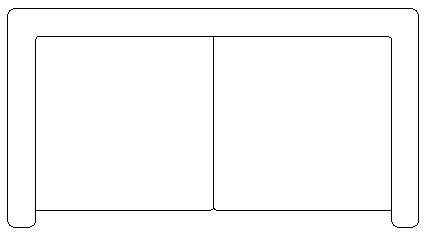
The second example shows the same geometry with the attributes
visible so that you see what the shapes represent.

The pictures above show a couch. The attributes describe
what the model number, color and cost are as well as
the manufacturer. From this simple example, you can see
that AutoCAD has a useful tool for showing more than
just geometry.
This example shows information about furnishings in an office.
Once you have drawn the floor plan, you could insert
blocks of furniture that have information about the manufacturer,
price, weight, and any other information you may need.
This information can then be extracted out of AutoCAD
and then used in a spreadsheet or other program which
could generate a Bill of Materials. Although you won't normally use the more advanced features of Attributes in your daily work, it's good to know how they work.
In this lesson you will be creating attributes and attaching
them to the computer block that you made previously.
Like everything you do in AutoCAD, there are particular
steps involved when you work with attributes.
-
First you have to define (or create) the attribute.
-
Next you will create the block with attributes.
-
Finally, when you insert the block you will give it the specific information
Many of the commands that you will be using are tough to remember
at first. You may find it easier to use icons (but then
the icons look very similar). Pull down menus are another
option, so you can see exactly what the command is that
you are starting.
Command |
Keystroke |
Icon |
Location |
Result |
Define an attribute |
ATTDEF / ATT |
 |
Home > Block > Define Attribute |
Creates an attribute definition |
Edit attributes |
DDATTE / ATE |
 |
Home > Block > Edit Attributes |
Edits the contents of an existing attribute |
Display Atts. |
ATTDISP |

|
Home > Block > Retain Display |
Hides or shows attributes |
Extract Attributes |
EATTEXT |
|
Insert > Linking & Extraction > Extract Data |
Extracts attributes using the wizard |
Open up the floor plans you drew earlier with the Computer
blocks in Lesson 2-2.
Insert a computer block and then explode it (type X <ENTER> and then select the block - press <ENTER>.)
Begin the Attribute definition command: ATT(or) ATTDEF (or) DDATTDEF
(AutoCAD has kept
the commands from previous versions active in the new
versions.)
Look at the dialog box below. Fill in the edit boxes just
like the example. Make sure to adjust the text height
if necessary.
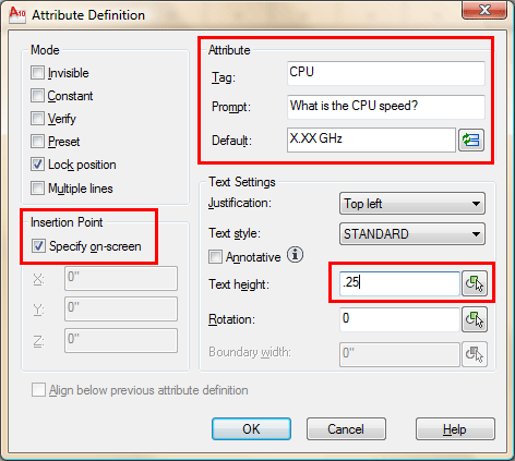
What you did is give the attribute its
definition - a name (tag), a prompt to help the user while they're inserting
it, and a (default) value for the prompt.  . .
Once everything is entered, select the OK button.
When you are back on the drawing screen, pick a point near
the middle of the computer block. When you are done,
the dialog box comes back so press OK.
Add the following attributes the same way, except instead
of picking a point, check off the Align
below previous attribute checkbox.
TAG |
PROMPT |
VALUE |
MONITOR |
What is the MONITOR SIZE? |
XX" |
HDD |
What capacity is the Hard Drive? |
X.XXGB |
RAM |
How much RAM is installed? |
XXXGB |
STATION |
What station is this |
XXX |
Once all the attributes are created you should have something like this:

Next you will create a block that includes your four attributes.
 Start up the BLOCK command.
Create it as shown in the previous lesson. When you select the Attributes, select them individually from top to bottom. When you are asked for the
block name, give it the name COMP-AT. Start up the BLOCK command.
Create it as shown in the previous lesson. When you select the Attributes, select them individually from top to bottom. When you are asked for the
block name, give it the name COMP-AT.
Insert the block and you will get a dialog box where you can
enter the values for the tags. You will be prompted
to provide answers to the prompts that you defined in
the attributes.

After inserting the block and answering all the prompts,
your block should look like this:

Now by looking at the drawing, you can
see exactly what type of computer it is and what station
(location) it is. This is just one application, but you can see how it can be used in any discipline of drafting. You can either insert more blocks, or copy the one that is in the drawing.
EDITING ATTRIBUTES
Of course, in any project, the data is subject to change.
In this example, the company may decide that it cannot
afford 24" monitors.
You can easily change the value of attributes within a
single block insertion by double-clicking on the block.
That will bring up this dialog box:

Remember that this will only edit the one
block that you double-clicked on. If you want to change
more than one block at a time to SAME values, you can select
the blocks, then select your blocks, right-click and choose Properties. Look for the Tag value you want to change and remember you are changing all values to the same one you input now.
DISPLAYING ATTRIBUTES
Sometimes you don't want to see the attribute values displayed
(say for plotting). You can turn them off. This can be
done by typing in the command ATTDISP and
then OFF. To turn them back on
again, type ATTDISP and ON.
It can't get much easier. You can also navigate the ribbon to Home > Block > Attribute Display and choose from these buttons.

EXTRACTING
ATTRIBUTE DATA IN AUTOCAD
So now you're
wondering what can you do with all of this information.
A CAD drawing can be used to track inventory and export
that data to another file (such as Microsoft Excel - a spreadsheet application) for others to use. Maybe the
purchasing department wants to know what to order, based
on the design you are working on.
Exporting the data became MUCH easier
in recent versions of AutoCAD.
Insert 6-12 of the blocks of the computer you made with Attributes and fill out the values .
Start up the EATTEXT command
and you will see the Data Extraction wizard dialog box appear. Accept the default setting of "Create a new data extraction" and press Next. You should be prompted to save your "Data extraction files as...". Select a folder and name the file "attributes_001". This will take you to step 2 of 8. This is where you tell AutoCAD what drawings you want to extract data from.

You will have the option here to add more drawings (not in this example), but make sure that "Select objects in current drawing" is selected, and then use the icon to select the blocks that you want to include in this extraction. When you are done, press Next.
Now you need to tell AutoCAD what objects in the drawing you want to include in the extraction.

Check the box for "Attributes" and you should see that the only item in the list is your Computer block. Press Next.
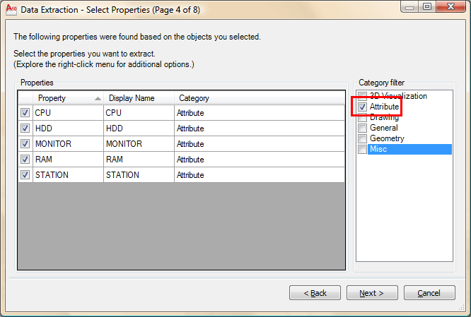
So far in each step you have narrowed the criteria for extraction from which drawings, to which blocks, and now you can select which attributes you want to extract. Press Next.

This step allows you to further filter and organize the data you want. You should have 2 extra columns than what is shown above - right click on the extra column and select "Hide Column". Next, select the column header for "Station" and drag it over to the right (this is to define the order of display which you'll see soon). Finally sort the Station column by clicking on the column header. Your dialog box should look like the one above now. Press Next.
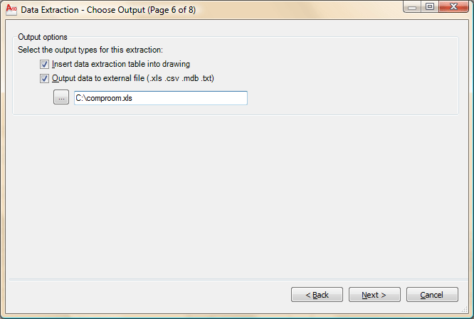
On the next step, select both boxes, and choose a location to save the file to. Press Next.
Step 7 allows you to format the table that will be created in the drawing. Table are covered in another tutorial. Add a title for your drawing called "Computer Stations". Select the box for "Use property names as additional column headers". Press Next.
Read the instructions on the final step. In this example you chose to include a table so you will be prompted to select an insertion point after you click Finish. Press Finish, and your insertion point and you should have a table that looks like this:
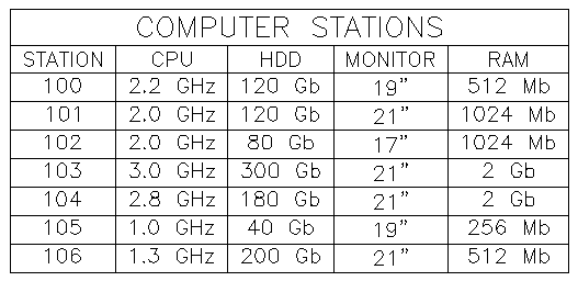
Now you have a Excel file on your computer showing the data from the drawing (open it if you have Excel). You also have a table that is still linked to the blocks in your drawing. Edit the attributes in a few of your blocks. Then right-click select a line in the table (not text) and select "Update Table Data Links". Deselect your table and you will see that it is now updated with the most recent block data.
For more about tables in AutoCAD, please refer to lesson 4-9.
This is just a simple walkthrough of some
of the power of AutoCAD. With more complex drawings and
attributes, you can work wonders. Think about how easy it would be to build a table of all windows in a house plan if the windows were created as blocks with attributes. Some assembly drawings consist of nothing but standard blocks, this lesson shows how much this simple process of creating attributes would help the workflow. Attributes are powerful - remember to use them.
In everyday work, your exposure to attributes may be minimal. Still you might find yourself inserting blocks and entering some data, and now thanks to this exercise, you know the power of attributes. Get to know how this works and you can really impress your boss!
Extra Practice: Here is an exercise for creating a title block with attributes. This is a handy item to have. It allows you to quickly enter the data for the title block using attributes, rather than create text every time. Link to the exercise. You could then use the information in the Title Blocks to create a file showing information about all the drawings on your computer by extracting the data.
|