There is only one way to get better at AutoCAD and that
is to practice. In 3D, you not only need to know the commands,
but also how best to use them. As you start drawing in
3D, you may start looking at everyday objects and think
about how they would be drawn. Look at the sample drawing
page and think about how they were done - using only the
commands shown in this level.
EXTRA PROJECT - A
If you have finished the previous exercises and would like
more practice, try this:
Sketch out a simple coffee table on paper.
Add the basic dimensions. Draw this in AutoCAD using any
3-D method. Once you've done this, draw another lamp and
place it on the table. Use rotate3d if
you need to turn it right-side up. Find a good view to
display what you have drawn. Add materials.
EXTRA PROJECT - B
Take your file from Lesson
3-7 that gave you a solid model and use the fillet
and chamfer commands to add some smoother corners to
your chair.

EXTRA PROJECT - C
Draw the object that you draw in the isometric lesson in 3-D
using extruded regions. You will have to first create
the outline, then the circle. Turn both objects into
regions. Subtract the circle from the outline to have
one remaining region. Extrude this to get your solid
object.
TUTORIAL - CREATING A 3D OBJECT FROM A 2D PROFILE
For this tutorial, you should be familiar with these commands: region, extrude, union, subtract.
This tutorial shows
you a method for quickly turning 2D shapes into 3D objects.
One of biggest problems with 2D objects is that they
are not always drawn properly. This is something that
should have been addressed when it was first drawn, but
here is a way of working around it.
First lets start with
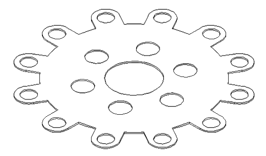
a basic shape (remember the array command). This is the profile for a gasket. It is
drawn in 2D with lines, arc and circles.

Let's hope it was well drawn,
meaning no overlapping lines, gaps, etc. Copy the objects over to the side for the next section.
Here is how
you turn it into a 3D object easily. Start the REGION command.
Draw a crossing window around the whole area and press
enter. Once you have your regions created, you can extrude
them. Start the EXTRUDE command
and select all objects. Press enter and enter your extrusion
height and taper angle. When these are extruded, begin
your SUBTRACT command
and first select the larger object first (to be subtracted
from), press enter then select all the other objects
and press enter. When you change to your SW Isometric
view, type in HIDE (enter)
and you should see the object as shown below.

Remember that you can always work in your SW Isometric view to
see the progress of your 3D work.
There is one problem
when using the REGION command.
If have two lines that are overlapping, AutoCAD can not
make a region out of the objects. You could search until
find the offending line, but there is an easier way.
Here's this approach:
Now look at the copy of the shape that you made you earlier. Instead of using the
region command, use the BPOLY command.
This command works similar to the HATCH command
in that it finds the boundaries for you. Start the command
and you will see this dialog box come up:

Accept the defaults
and press on the Pick Points button. In your drawing
screen, pick an internal point as if you were hatching
it and then press enter.
Now start your EXTRUDE command
and select the last (L) object created and extrude it. Now begin the SUBTRACT command
and select the outside object, (press enter) then use
a crossing box to select everything else and press enter.
Use the HIDE command
to ensure that everything is as it should be.
|