For the next few lessons, you should switch to the 3D modeling workspace. Look for the icon in the bottom right of the AutoCAD screen.

What is a Primitive Solid?
A primitive solid is a ‘building block' that you can use
to work with in 3D. Rather than extruding or revolving
an object, AutoCAD has some basic 3D shape commands at
your disposal. From these basic primitives, you can start
building your 3D models. In many cases, you get the same
result from drawing circles and rectangles and then extruding
them, but doing it one command is generally faster. Using
these with Boolean operations can be a very effective
way of drawing in 3D. There are eight different primitives
that you can choose from and are on the Home > Modeling Tool Panel (when in the 3D workspace).
(Click
on the ICON below to go to the command)
SHAPE |
COMMAND |
ICON |
DESCRIPTION |
BOX |
BOX |

|
Creates a solid box after you provide 2 opposite corners and a height. |
SPHERE |
SPHERE |

|
Creates a solid sphere from a center point and radius. |
CYLINDER |
CYLINDER |

|
Creates a straight cylinder from a center point, radius and height. |
CONE |
CONE |

|
Creates a tapered cone from a center point, radius and height. |
WEDGE |
WEDGE |

|
Creates a triangular wedge from 2 opposite points. |
TORUS |
TORUS |

|
Creates a torus (donut shape) based on center point, radius
and tube radius. |
PYRAMID |
PYRAMID / PYR |
 |
Draws a solid object with a polygon (3-32 sides) base that rises to a central point. |
POLYSOLID |
PSOLID |
 |
Draws a solid object with width and height as you would draw a polyline. |
You can use primitives to either begin building a model,
or it can even be a finished object on its own. Many
of these commands are similar to 2D commands, except
with an extra coordinate in the Z axis. Here is a summary
of working with these commands.
BOX

Think of a box as an extruded rectangle. It has width, height
and depth. It is created by establishing a starting corner
and then establishing a second corner by either picking
or giving relative coordinates.
Here is an example of this:
Command: box
Specify corner of box or [Center]: 2,3,4
Specify corner
or [Cube/Length]: @5,7,10
This
draws a box that is 5 units in the X-axis wide, 7 units long
in the Y-axis and has a depth of 10 units in the
positive Z-axis with one corner located at 2,3,4.
Here
is another way of drawing that same box:
Command: BOX
Specify
corner of box or [Center]: 2,3,4
Specify
corner or [Cube/Length]: @5,7
Specify
height: 10
Using this method, you establish the first corner as before,
but only enter the X and Y coordinates of the opposite
corner. AutoCAD will then prompt for the height.
Another
way of drawing a box is to establish where the center
of the box will be:
Command: BOX
Specify
corner of box or [CEnter] <0,0,0>: C
Center of box <0,0,0>: <ENTER> or <PICK A POINT>
Specify corner or [Cube/Length]: @2,3,4
This
draws a box that is 4x6x8 based about the center of 0,0,0.
If
you want to draw a perfect cube, you can use this option:
Command: BOX
Specify corner of box or [CEnter]<0,0,0>: <pick
point>
Specify
corner or [Cube/Length]: C
Length: 4
This draws a cube with all sides equal to 4 units based of
off a picked point.
The last way of drawing a cube allows you to enter the Length,
Width and Height as separate distances, and not based
on coordinate points.
Command: BOX
Center/<Corner
of box> <0,0,0>:
Cube/Length/<other
corner>: L
Length: 5 <X AXIS>
Width: 4 <Y AXIS>
Height: 6 <Y AXIS>
Of course you can also draw a box by picking two opposite
corners with your mouse. This is useful for filling in
areas and can be very quick. Make sure to use your Osnaps.
SPHERE

A Sphere is a globe-like shape. It is very similar to drawing
a circle in that you pick a center point and then input
either the radius (default) or diameter. Both methods
draw the same sphere in the following examples:
Command: SPHERE
Specify center point or [3P/2P/Ttr]: <PICK POINT>
Specify radius or [Diameter] <2.3756>: 6 <ENTER>
Command: SPHERE
Specify center point or [3P/2P/Ttr]: <PICK POINT>
Specify
radius of sphere or [Diameter]:D
Specify Diameter: 12
Both of the above methods will give you the same result.
You also have the options of selecting 3 Points, 2 Points, or using 2 tangents and radius (TTR).
CYLINDER
A cylinder is just like an extruded circle. Creating one
is very similar to creating a circle, except that you
are giving depth to it.
These two examples would draw the same cylinder:
Command: CYLINDER
Current wire frame density: ISOLINES=4
Specify center point for base of cylinder or [Elliptical] <0,0,0>:<PICK POINT>
Diameter/<Radius>: 2.5
Center
of other end/<Height>: 1.2
Command: CYLINDER
Current
wire frame density: ISOLINES=4
Specify center point for base of cylinder or [Elliptical] <0,0,0>:<PICK POINT>
Specify radius for base of cylinder or [Diameter]: D
Diameter: 5
Specify height of cylinder or [Center of other end]: 1.2
CONE
Drawing a cone is the same as drawing a cylinder, except
that the resulting object tapers smoothly from the bottom
to a point at the top.
Command: CONE
Current
wire frame density: ISOLINES=4
Specify center point for base of cone or [Elliptical] <0,0,0>:
Specify
radius for base of cone or [Diameter]: 4
Specify
height of cone or [Apex]: 8
Command: CONE
Current wire frame density: ISOLINES=4
Specify center point for base of cone or [Elliptical] <0,0,0>:
Specify
radius for base of cone or [Diameter]: D
Specify
diameter for base of cone: 8
Apex/<Height>: 8
Another way of drawing a cone is to enter in the center point,
the radius (or diameter) and then establish where you
want the apex (point of cone) to be. You can either type
in coordinate points or pick a point with your cursor.
Command: CONE
Current
wire frame density: ISOLINES=4
Specify center point for base of cone or [Elliptical] <0,0,0>:<PICK>
Specify
radius for base of cone or [Diameter]: 5
Specify
height of cone or [Apex]: A
Specify
apex point: @5,5,6
WEDGE
One of the trickier primitives to draw is the wedge. You
have to be careful which coordinates you input to make
the wedge lie in the position you want. If it doesn't
turn out just as you hoped for, you can always rotate
it.
Here is an example of drawing a wedge:
Command: WEDGE
Specify
first corner of wedge or [CEnter]<0,0,0>: <PICK>
Specify
corner or [Cube/Length]: @5,2,4
Once
the first corner is established, you can either enter
points, or pick a spot. AutoCAD will draw the shape like
it would draw a cube except it is slice in half along
the length starting at the point above the first corner.
There are other options to drawing wedges and see the
box examples for these.
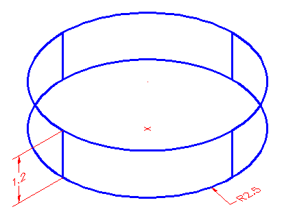
TORUS
A
torus is a donut-like shape or something resembling an
inner tube. When drawing one you have to enter the center
point, a radius to the center of the tube and the radius
of the tube itself.
Command: TORUS
Current
wire frame density: ISOLINES=4
Specify center of torus <0,0,0>:
Specify
radius of torus or [Diameter]: 3
Specify
radius of tube or [Diameter]:.25
The
diagram above shows the resulting diameters from
the input above. A center mark indicates the picked center
of the torus.
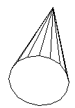
PYRAMID 
To draw a pyramid, you need to know the diameter of the base and the height. The diameter can either be inscribed (inside the circle) or circumscribed (outside the circle). You can define the number of edges to from 3 to 32.
Command: PYR
PYRAMID
5 sides Inscribed
Specify center point of base or [Edge/Sides]:
Specify base radius or [Circumscribed] <4.5655>: C
Specify base radius or [Inscribed] <4.5655>: I
Specify base radius or [Circumscribed] <4.5655>: 4
Specify height or [2Point/Axis endpoint/Top radius] <10.0108>: 9
In the above example, I showed how to switch between Inscribed or Circumscribed as the options change depending upon the method selected.
Try creating some pyramids using a variety of methods.
POLYSOLID 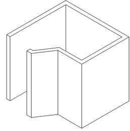
This is a new command since AutoCAD 2007. A polysolid allows you to draw a solid object while defining the height and the width. I think this command is aimed at the architects, who will enjoy the ability to quickly draw solid walls.
Command: PSOLID
POLYSOLID Specify start point or [Object/Height/Width/Justify] <Object>: H
Specify height <96.0000>: 96
Specify start point or [Object/Height/Width/Justify] <Object>: W
Specify width <6.0000>: 6
Specify start point or [Object/Height/Width/Justify] <Object>: J
Enter justification [Left/Center/Right] <Center>: L
Specify start point or [Object/Height/Width/Justify] <Object>: <Pick 1st point>
REVIEW
As mentioned in previous lessons, solids are usually the
way to go with 3D CAD. Depending upon your chosen field,
you may use 3D meshes in Civil Drafting, Isometric in HVAC,
solids in mechanical, etc.
I recommend getting used to solids if you are doing any
kind of mechanical drafting or architectural drafting if
you are using base AutoCAD software. When using solids,
you will usually take a shape and extrude it - then use boolean
commands and others to edit it. Here is a basic building that was quickly drawn using a variety of primitive solids.

Extra Practice: Draw some primitive solids using the dimensions shown above or make up your own. Try to create a building out primitive solids.
|